The Essential Bus has the highest level of integrity and under normal conditions it is powered from:
It can be supplied with power from either generator or both batteries.
Generator 2 is the primary power source for the Channel 2 Secondary Power Line and the Main, Avionic 2, Non-Essential and Cabin Buses. Generator 2 is also the engine starter motor. If the engine STARTER switch is pushed to ON and the engine Ng is less than _____ the generators are automatically switched OFF.
The Hot Battery Bus is powered directly from _____.
It supplies power to systems that must remain powered or available when the aircraft is powered down.
There is a Battery and External Power Junction Box (BEPJB) which contains the components for the batteries, external power functions, hot battery bus and associated circuit breakers. It also contains the necessary components to permit optional nickel cadmium batteries to be installed. The BEPJB is installed in the rear fuselage of the PC-12.
In the event of a total power loss (both generators and batteries) the Emergency Power Supply (EPS) battery will provide sufficient power thru the EPS bus to the backup systems for _____.
An External Power caution is displayed in the CAS window if ground power is still connected and:
The Essential Bus will always be powered under normal, abnormal and emergency conditions. There are no relays or contactors controlling the Essential Bus.
Following the loss of generator and battery power to the Essential Bus the EPS battery will provide power to the standby instruments. The red EPS ON indicator on the overhead control panel will come on.
The Cabin Bus has the fourth highest level of integrity and under normal conditions it is powered from Generator 2. When either generator is off-line the Cabin Bus is unpowered. The Cabin Bus provides power for ancillary non-flight related services within the cabin. All these services are shed in the event of a single generator failure.
The EPS should be checked prior to flight by moving the EPS switch on the overhead control panel to the TEST position. The green TEST indicator comes on to indicate a serviceable electrical system.
The green TEST indicator comes on to indicate a serviceable battery.
Advertisement
The Power Line is the primary source of electrical power with the highest level of integrity. It supplies the Essential and Avionic 1 Buses and power for:
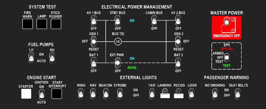
The MASTER POWER EMERGENCY OFF switch is guarded to the on position. When the switch is selected off the Generator 1 and 2, Battery 1 and 2 and external power are disconnected from the distribution system. The Standby Power Bus is de-energized.
In case of an engine or double generator failure, the batteries will supply the essential electrical systems after automatic load shedding for a maximum range glide and one attempted engine start. This is the Power Generation Distribution System (PGDS) emergency operating condition.
Following the loss of generator and battery power to the Essential Bus the EPS battery will provide power to the standby instruments. The red EPS ON indicator on the overhead control panel will come on.
Under normal, abnormal and emergency conditions the EPS battery is connected to the Essential Bus to maintain a maximum charge. Following the loss of the Essential Bus the EPS Bus automatically switches to be supplied from the EPS battery.
Battery 2 provides the power for starting the engine. Battery 1 provides power to maintain the essential systems during engine start and on ground supplements Battery 2 for engine starting at either _____ after the starter is activated.
There are two Power Junction Boxes (PJB), one for each battery.
There are two Power Junction Boxes (PJB), one for each generator. Generator 1 PJB is installed on the cockpit lower left wall and Generator 2 PJB is installed on the cockpit lower right wall. They contain the principal contactors, relays and other circuit protection devices.
On ground the DC system can be powered by an external power unit which is connected under the rear fuselage left side. An External Power Controller (EPC) monitors external power supply and automatically isolates the aircraft systems if the voltage is outside the range _____
The EPC will disconnect external power if either generator is on-line.
The Modular Avionics Unit (MAU) provides monitoring of the battery voltage and current. A decrease of battery voltage below _____ will give a Battery caution.
When the engine is running, Generator 1 is the primary power source for the Channel 1 Power Line, and the Essential and Avionic 1 Buses. The Standby Bus is powered from the Avionic 1 Bus.
If the Avionic 1 Bus is switched OFF, the Standby Bus is powered from the Hot Bat Bus provided the STBY BUS switch is set to on.
Advertisement
Should either the Generator 1 or Generator 2 fail, the control relays in the Power Generation Distribution System (PGDS) automatically change and connect the remaining generator and both batteries to the Power and Secondary Power Lines. A warning will be displayed in the Crew Alert System (CAS) window.
It is not a warning but a caution only. This is the PGDS abnormal operating condition.
The Modular Avionics Unit (MAU) provides monitoring of the battery voltage and current. An increase of battery current above _____ discharge will give a Battery caution.
The CAS window on the systems MFD displays the following WARNINGS and CAUTIONS for the PGDS. What is the meaning of a 'BUS TIE' amber caution?
Battery 1 and Battery 2 are installed:
On ground the DC system can be powered by an external power unit. With both generators off-line the Bus Tie is closed, and ground power is fed to all aircraft busses and battery 1 only.
Ground power is fed to all aircraft busses and both batteries.
The Non Essential Bus has the fourth highest level of integrity and under normal conditions it is powered from Generator 1. When either generator is off-line the Non Essential Bus is un-powered.
Under normal conditions the Non Essential Bus is powered from Generator 2. When either generator is off-line the Non Essential Bus is un-powered. The Non Essential Bus provides power to equipment that may be shed in the event of a single generator failure.