Fuel Synoptic Indications - What does this indicate?
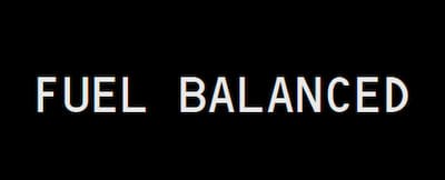
Due to the unique shape of the 787 composite wing, fuel quantity indications can fluctuate significantly (especially at low fuel loads) during:
How is the fuel quantity measured and monitored?
Surge tanks are provided in each wing, outboard of each main tank. Fuel in the surge tanks and fuel remaining in the refueling manifold is drained into:
In flight, jettison time is displayed in minutes on the fuel synoptic when the jettison arm switch is positioned on while in the air. Jettison automatically stops when the FUEL TO REMAIN quantity is reached.
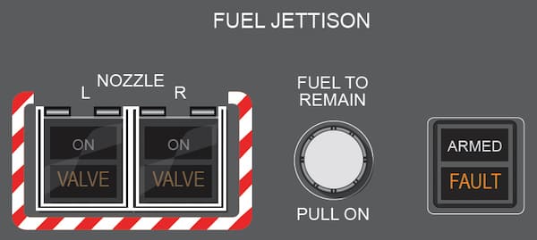
Jettison automatically stops when a value just above the FUEL TO REMAIN quantity is reached. Then the system will close the defuel-isolation valves and the jettison isolation valves.
Fuel Synoptic Indications - What does this indicate?
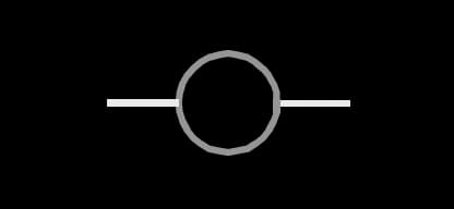
The fuel balance system is initiated by pushing the fuel balance switch. What is the true statement?
Manual crossfeed is initiated by opening the crossfeed valve and turning off the fuel pump switches for the fuel tank that has the lower quantity. Crossfeed may be done in any phase of flight.
At least _____ of fuel remains in each main tank after jettison is complete.

Where can the flight crew monitor fuel lines and fuel status?
Maximum tank fuel temperature at takeoff for Jet A, Jet A1,JP-5, JP-8 or TS-1 is:
Advertisement
The left main tank contains a DC–powered fuel pump. The DC pump operates:
It has no controls or indicators, other than the fuel synoptic display.
Expanded fuel indications showing the left main, center and right main tank quantities are displayed at all times.
Expanded fuel indications showing the left main, center, and right main tank quantities are displayed when non-normal conditions occur.
Fuel Synoptic Indications - What does this indicate?

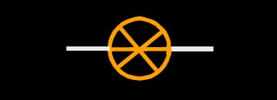
Fuel Pump (green rectangle with line).
Fuel Synoptic Indications - What does this indicate?
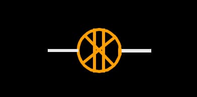
The fuel jettison nozzles cannot open on the ground, regardless of switch positions.
Prior to takeoff tank fuel temperature must not be less than:
Each fuel tank contains one AC and one DC–powered fuel pumps. A single pump can supply sufficient fuel to operate one engine under all conditions.
Each fuel tank contains two AC–powered fuel pumps. A single pump can supply sufficient fuel to operate one engine under all conditions.
With the main tank pumps ON, a scavenge system operates automatically to transfer any remaining center tank fuel to the main tanks. Fuel transfer begins when either main tank quantity is less than approximately _____(depending on fuel density) and the center tank pumps are off.
The system is inhibited if the engine is on suction feed.
During jettison, the TO REMAIN quantity replaces the EICAS display static air temperature and fuel temperature indications.

Fuel temperature and minimum fuel temperature are also displayed on the fuel synoptic display.
Where does the APU normally draw fuel from?
Advertisement
Fuel Synoptic Indications - What does this indicate?
Main tanks must be scheduled to be full if center tank fuel is loaded.
Note : The center tank may contain up to 10000 kilograms of fuel with less than full main tanks provided center tank fuel weight plus actual zero fuel weight does not exceed the maximum zero fuel weight, and center of gravity limits are observed.
The two center tank fuel pumps are override-jettison pumps. These pumps have a:
The center tank pumps override the main tank pumps so that center tank fuel is used before wing tank fuel.
Expanded fuel indications showing the left main, center, and right main tank quantities are displayed when non-normal conditions occur.
Fuel quantity is measured by sensors in each tank. Total fuel quantity is displayed on the secondary EICAS display. Tank quantities and total fuel quantity are displayed on the FUEL synoptic display.
Fuel quantity is measured by sensors in each tank. Total fuel quantity is displayed on the primary EICAS display. Tank quantities and total fuel quantity are displayed on the FUEL synoptic display.
Anytime the Crossfeed valve is open, the amber VALVE light illuminates and the EICAS Advisory message of FUEL CROSSFEED is displayed.
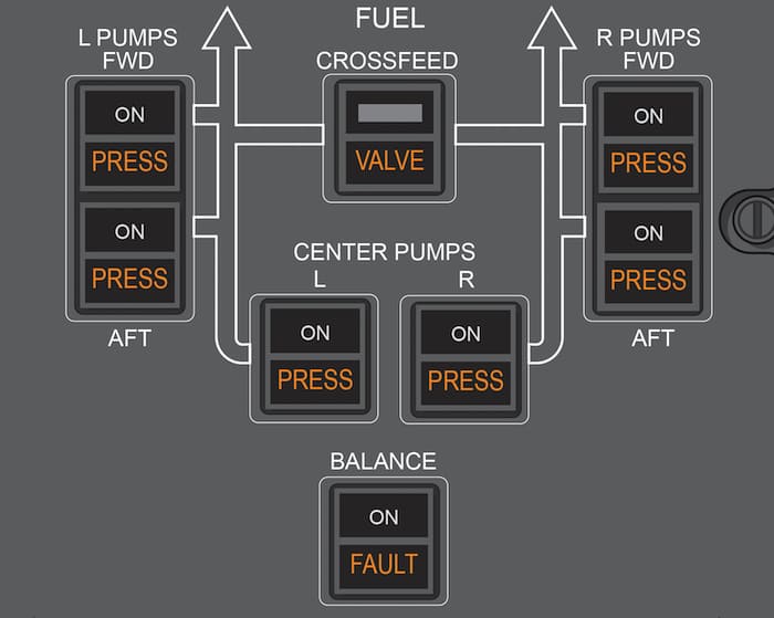
Anytime the Crossfeed valve position does not agree with the CROSSFEED switch position, the amber VALVE light illuminates and the EICAS Advisory message of FUEL CROSSFEED is displayed.
On the ground, with the APU switch ON and no AC power available, the DC pump runs automatically. With AC power available, the left aft AC fuel pump operates automatically, regardless of fuel pump switch position, and the DC fuel pump turns off.
When less than all engines-generators are operating, there may not be sufficient electrical power to operate all fuel pumps. In such cases:
Certain fuel pumps may be load shed until enough electrical power is available. The indications that a fuel pump has load shed are that the pump switch PRESS light is illuminated and the pump is labeled LOAD SHED on the fuel synoptic.
When the main tank fuel pump switches are off, the switch PRESS lights illuminate and the EICAS advisory messages FUEL PUMP (L, R, FWD, or AFT) display. When the center fuel pump switches are off, the switch PRESS lights and pump pressure EICAS messages are inhibited.
In-flight tank fuel temperature must be maintained at least -42 deg.C, as well as 3 deg.C above the freezing point of the fuel being used.
The use of Fuel System Icing Inhibitor additives does not change the minimum fuel tank temperature limit.
