Using the Standby Hydraulic power for thrust reverser deployment will cause:
If one FLIGHT CONTROL switch is moved to STBY RUD:
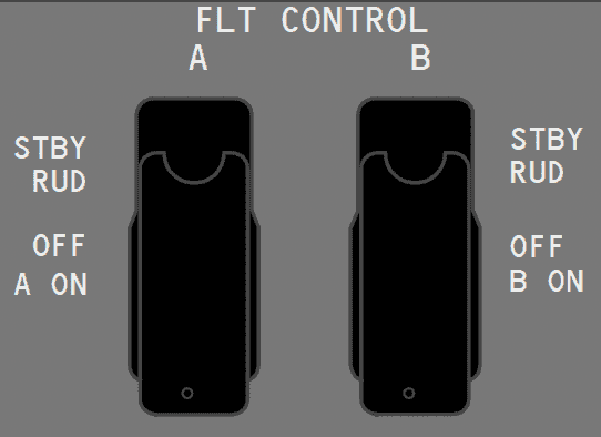
In addition to hydraulic system A and B, the rudder can also be powered by the standby hydraulic system through the:
Landing Gear Transfer Unit - The system B engine-driven pump supplies the volume of hydraulic fluid needed to operate the landing gear transfer unit when all of the following conditions exist:
Standby Hydraulic System - The standby hydraulic system is provided as a backup if system A and/or B pressure is lost. The standby system can be only activated automatically.
The standby system can be activated manually or automatically.
An engine-driven hydraulic pump supplies approximately _____ the fluid volume of the related electric motor-driven hydraulic pump.
System B Hydraulic Leak - A leak in system B can significantly affect the operation of the standby hydraulic system.
A leak in system B does not affect the operation of the standby hydraulic system.
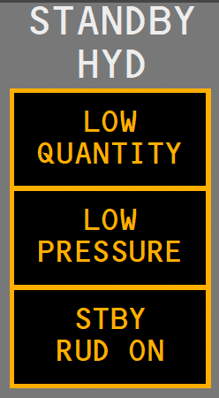
STANDBY HYDRAULIC LOW QUANTITY Light - What is the true statement?
In case of loss of system A:
Hydraulic fluid used for cooling and lubrication of the pumps passes through a heat exchanger before returning to the reservoir. The heat exchanger for system A is located in main fuel tank No. 2 and for system B is in main fuel tank No. 1.
The heat exchanger for system A is located in main fuel tank No. 1 and for system B is in main fuel tank No. 2.
Advertisement
The standby hydraulic pump only supplies pressure to the:
If a total failure of both pumps supplying system B pressure occurs, which of the primary flight controls will be totally inoperative:
STANDBY HYDRAULIC LOW PRESSURE Light - When illuminated amber:

Minimum fuel for ground operation of electric motor-driven pumps is _____ in the related main tank.
STBY RUD ON Light - When illuminated amber, it indicates the standby hydraulic system is commanded on to pressurize the standby rudder power control unit.

Standby Hydraulic System Leak - If a leak occurs in the standby system, the standby reservoir quantity decreases to _____
The ELEC 2 (system A) or ELEC 1 (system B) pump ON/OFF switch controls the related electric motor-driven pump. If an overheat is detected in either system, the related OVERHEAT light illuminates.
System A Hydraulic Leak - If a leak develops in the electric motor-driven pump or its related lines, or components common to both the engine and electric motor-driven pumps:
Both A and B hydraulic systems have an engine-driven pump and an AC electric motor-driven pump. The system A engine-driven pump is powered by the No. 2 engine and the system B engine-driven pump is powered by the No. 1 engine.
The system A engine-driven pump is powered by the No. 1 engine and the system B engine-driven pump is powered by the No. 2 engine.
The hydraulic brake pressure indicator displays accumulator nitrogen pre-charge pressure of 1000 psi and:
Advertisement
The standby system LOW PRESSURE light is armed:
With the loss of hydraulic system B and with the system A operating normally:
The RFF indication is displayed:
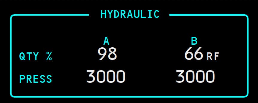
The 737NG/MAX 'B' system reservoir has:
The normal and maximum readings on the hydraulic system pressure indicator are:
On the Boeing B737 NG/MAX, a leak in the hydraulic system B engine driven pump or its associated lines would be indicated by:
Complete loss of system 'B' pressure will deactivate:
The amber LOW pressure light for the No.1 Engine Driven Hydraulic Pump illuminates. What should you do?

Loss of an engine-driven hydraulic pump and a high demand on the system may result in an intermittent illumination of the LOW PRESSURE light for the remaining electric motor-driven hydraulic pump.
Low fluid quantity in the A system reservoir can be indicated by one of the following:
Advertisement
ALTERNATE FLAPS Master Switch - When placed in the ARM position, the ALTERNATE FLAPS Master switch:
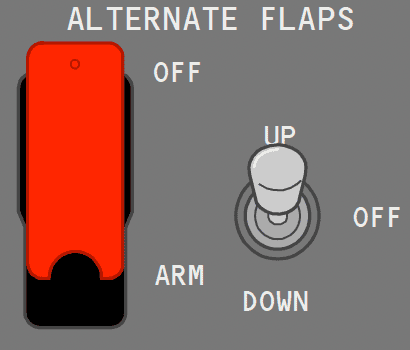
The standby hydraulic system uses a single electric motor-driven pump to power:
Variations in Hydraulic Quantity Indications - During normal operations, variations in hydraulic quantity indications occur when:
These variations have little effect on systems operation.
Loss of an engine-driven hydraulic pump and a high demand on the system may result in an intermittent illumination of the LOW PRESSURE light for the remaining electric motor-driven hydraulic pump.
The flight control LOW PRESSURE light, Master Caution light, and the FLT CONT and HYD system annunciator lights also illuminate.
Power Transfer Unit (PTU) - The PTU uses system B pressure to power a hydraulic motor-driven pump, which pressurizes system A hydraulic fluid.
Power Transfer Unit (PTU) - The purpose of the PTU is to supply the additional volume of hydraulic fluid needed to operate _____ when system B engine-driven hydraulic pump volume is lost.
System A Hydraulic Leak - If a leak develops in the engine-driven pump or its related lines, a standpipe in the reservoir prevents a total system fluid loss. With fluid level at the top of the standpipe, the reservoir quantity displayed indicates approximately _____
System A hydraulic pressure is maintained by the electric motor-driven pump.
The Standby hydraulic fluid:
Standby Hydraulic System Leak - The LOW QUANTITY light illuminates when the standby reservoir:
Selecting an engine driven hydraulic pump switch to OFF will:
Advertisement
Electric Hydraulic Pump OVERHEAT Lights - What does this light indicate?

The maximum hydraulic system A or B pressure is:
If the hydraulic system is not properly pressurized, foaming can occur at higher altitudes. Foaming can be recognized by:
Standby Hydraulic System Leak - System B continues to operate normally, however, the system B reservoir fluid level indication decreases and stabilizes at:
System A Hydraulic Leak - If a leak develops in the engine-driven pump or its related lines, a standpipe in the reservoir prevents a total system fluid loss. With fluid level at the top of the standpipe, the reservoir quantity displayed indicates approximately _____
System A hydraulic pressure is maintained by the electric motor-driven pump.
