The fuel quantity indicating system informs the crew of the quantity of fuel available in each tank during flight. The quantities are processed by the _____ and displayed on MFD.
The temperature sensor is in the right feeder compartment.
The temperature sensor is in the left feeder compartment. Temperature appears on MFD.
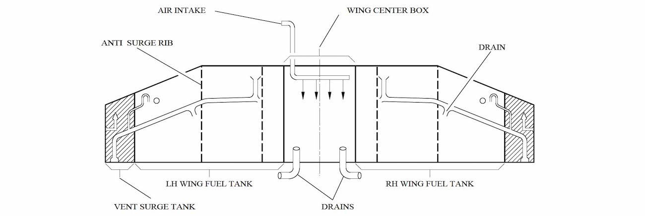
Two tanks receive fuel, one in each wing. Tanks are integral part of the wing structure. At a fuel density of 0.785 the maximum fuel capacity is:
An additional volume in each tank enables a 2 % fuel thermal expansion without spillage. Each tank has two access doors on the upper wing skin. These four doors at each tank extremity enable access to the interior and essential equipment.
In case of quantity indicating system failure, on ground, there is one magnetic level indicator in each tank through the lower wing skin give fuel quantity. Tables provide fuel mass with corrections established for aircraft attitude and fuel density.
There are two magnetic level indicators in each tank through the lower wing skin give fuel quantity. Tables provide fuel mass with corrections established for aircraft attitude and fuel density.
The vent system ensures positive pressure in the entire flight envelope. Each fuel tank is ventilated via an individual vent duct and also with a vent float valve connected to a _____ surge tank in the outer section of the wing.
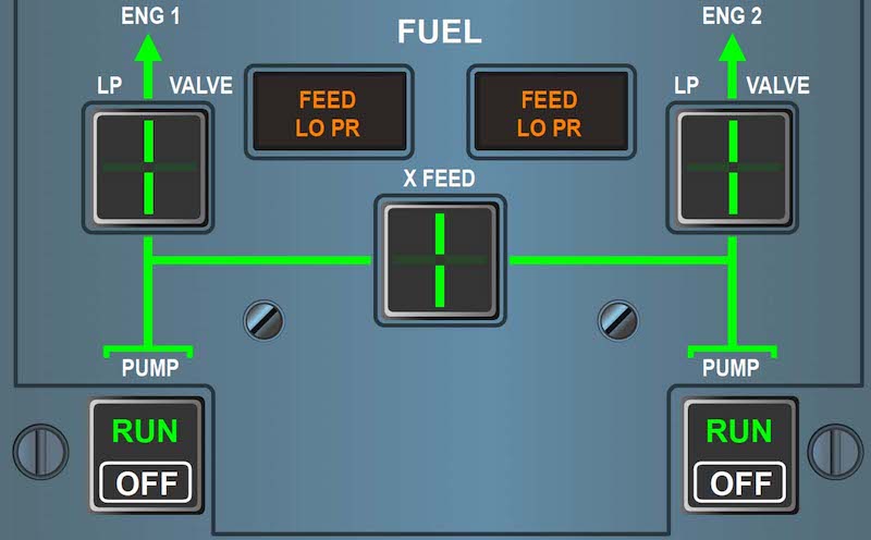
LH and RH fuel pumps are running. To feed engine 1 with tank 2, you must:
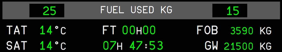
Fuel On Board Indication - In normal operation, values are displayed in green with kg/lb unit. For invalid data:
A flush NACA inlet connects surge tank to atmosphere and avoids icing obstructions. A surge tank collects fuel and enables fuel return to the wing tank via the vent duct.
The vent system also provides protection for the tanks in case of accidental spillage during refueling.
What power source supplies the refuel/defuel panel?
Two electrically operated actuators control the crossfeed valve. This valve enables both engines to be fed from one side or one engine to be fed by either tank and avoid unbalance situation.
There is only one electrically operated actuator that controls the crossfeed valve. Crossfeed valve indication is on both Fuel panel and MFD. When the crossfeed valve is open, a cyan 'FUEL X FEED' label appears on memo panel display and indication appears on the MFD system page.
Advertisement
A FUEL UNBALANCED alert is displayed when there is a discrepancy greater than _____ between left and right tanks fuel quantities.
ENG 1 and ENG 2 electrical pumps are supplied by the:
In normal conditions, each wing tank supplies their associated engine. The flight crew can monitor the fuel consumption for each engine with the fuel flow and fuel used parameters which are displayed on the MFD ENGINE page and EWD Permanent Data window. To prevent negative or lateral 'g' factor effect, a _____ always full of fuel is embedded in each tanks.
The wing center box over the fuselage hosts the collective surge tank. This box crossed by two fuel pipes, enables engine feed and tanks refueling.
The wing center box over the fuselage does not store any fuel. Ventilation and drainage prevents fuel vapor concentration.
FEED LO PR Light - In case of fuel delivery pressure below 4 psi, the light comes on amber. Also the caution message FEED LO PR is displayed on EWD with a Master Caution light and a Single Chime. This indicates:
On ground, when _____ , for aircraft servicing, GND HDLG BUS supplies FCU.
Water drainage are at the low points of each tank. Drainage operation can be performed up to a _____ ground slope.
One electrical pump and one jet pump are installed per feeder tank. High pressure fuel from the Hydro Mechanical Unit (HMU) activates the jet pump through the control of a motive flow valve. In normal operation, the electrical pump is only used to start the engine. After start, electrical pump is automatically shut down.
If jet pump pressure drops below 5 psi, the electrical pump automatically supplies the engine.