The three control channels of the FBW system are powered by independent power sources. If there is a DC bus power loss, the secondary power sources are from:
Maximum altitude with slats/flaps extended is:
When the autopilot is engaged, the forces that keep the sidesticks at their neutral positions are increased. If sufficient force is applied to either sidestick, the autopilot will disengage and the other sidestick will become free.
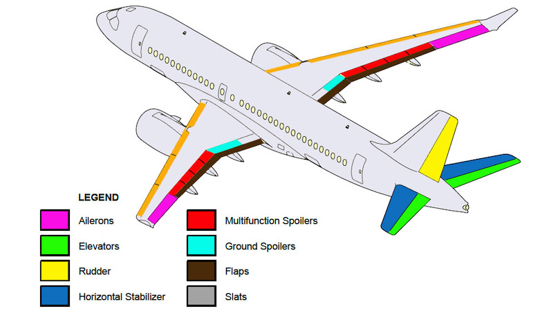
The Primary Flight Control System (PFCS) has two ailerons, two elevators, and a rudder. The secondary flight controls include:
The high-lift flight system has leading edge slats and trailing edge flaps. The primary and secondary control surfaces are hydraulically actuated. An electrically actuated horizontal stabilizer supplies longitudinal (pitch) trim.

Aileron lift augmentation - The ailerons deploy symmetrically (trailing edge down) for lift augmentation. The ailerons deploy from 0 degrees to 10 degrees as the flaps deploy, and retract on flap retraction.
The slat system can be operated with one motor and/or one hydraulic system inoperative. If this happens, the slats will reach the full deployment position, but at half the speed.
Spoiler operation on landing - The spoilers are armed for deployment on the ground when wheel speed is greater than _____.
An integrated Fly-By-Wire (FBW) system controls and monitors all primary and secondary flight controls. This includes the high lift devices (leading edge slats and flaps).
An integrated Fly-By-Wire (FBW) system controls and monitors all primary and secondary flight controls, except for the high lift devices (leading edge slats and flaps). The FBW system receives input commands electronically from the flight deck controls (initiated by the pilot) or directly from the autopilot. It converts them into output commands to move the aircraft control surfaces.
High speed protection - The high-speed protection limits the aircraft speed if it exceeds VMO/MMO due to pilot inputs or upsets, by applying an Horizontal Stabilizer (HSTAB) nose-up bias and deploying the MFS under high g loads. It automatically recovers the aircraft to the trim speed if the sidestick is released to its neutral position during an overspeed condition. The high-speed protection is only active when:
Sidestick test - A sidestick test pattern (cross) is displayed on the FLT CTRL synoptic page when:
When the sidestick is moved, the blue dot should move in the same direction as the sidestick until the sidestick reaches the pitch and roll axis limits.
Advertisement
High Angle-Of-Attack (AOA) protection direct mode - In direct mode, the FBW system:
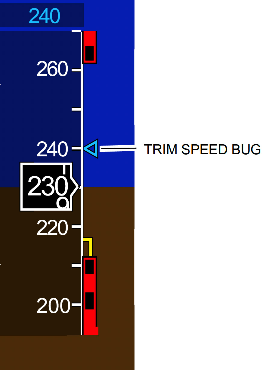
Manual speed trim - When the autopilot is disengaged, the trim speed is set manually with the pitch trim switch on the sidestick. The trim speed is displayed:

The sidestick shaker is inhibited below 100 kt.
The sidestick shaker is inhibited below 60 kt.
Normally, both sidesticks are active and can be used at any time. However, a priority can be assigned to either sidestick. The momentary priority is activated when the AP/PTY switch is:
When the switch is pressed and held, the sidestick has full authority, the opposite sidestick is deactivated, the PTY green legend on the onside glareshield SIDESTICK switch flashes, a red arrow is illuminated on the opposite SIDESTICK switch, and the autopilot disengages. A 'PRIORITY LEFT' or 'PRIORITY RIGHT' aural message sounds once each time the corresponding priority is selected. If both AP/PTY switches are pressed, the last one pressed has priority.
Roll/yaw protection function (bank angle limiting) - The bank angle is limited to _____ on each side.
During overspeed, or when the pitch is more than 10 degrees nose down, the bank angle limits are reduced for high speed protection and/or pitch limiting.
Aileron lift augmentation has priority over the Roll assist function.
It is the opposite: roll assist has priority over the aileron lift augmentation function.
When the rudder pointer is not green (centered) at takeoff:
Pitch control functions - The normal mode includes a speed stability function that uses pitch to automatically maintain a selected trim speed. If the aircraft speed moves away from the trim speed, the aircraft pitch changes to return to the trim speed.
Pitch control functions - In normal mode, the movement of the sidestick on the pitch axis commands a combination of pitch change rate and maneuver load factor. The neutral stick position corresponds to a demand of _____ flight with zero pitch rate.
In-flight engine out compensation - The intent of the engine out compensation is not to mask the engine failure, but to provide assistance in controlling the aircraft during and after the failure. The engine out compensation provides partial automatic yaw compensation with an engine out condition (in the air). This compensation is equally applicable to most failures that cause significant yaw. The aircraft typically rolls into the failed engine with a maximum bank angle of:
Advertisement
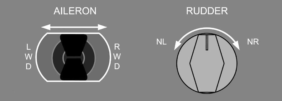
The trim panel, on the center pedestal, has the AILERON trim and RUDDER trim switches. The PFCC will disable the trim function if a trim switch is _____. Pilots are alerted with an aural alert (double beep) when they use the RUDDER trim switch. The timeout of the AILERON trim switches is not associated with an aural alert. When the trim switch is released, the trim function resets.

On the ground, when both thrust levers are advanced to more than 24 degrees, a nose-down elevator is applied to increase the load on the nose gear. With the sidestick at the neutral position (no pilot input), the elevator is automatically set to 12 degrees nose down up to:
The direct mode is automatically selected by the FBW system when the normal mode cannot be maintained. It is intended for continued safe flight and landing only. The direct mode is a command-by-wire system. The positions of the flight control surfaces are calculated based on direct mode control laws, allowing sidestick surface control with limited augmentation.
The direct mode provides limited pitch augmentation, while the aileron and rudder surface deflections are proportional to the lateral sidestick and rudder pedal inputs. DIRECT MODE is displayed in amber on the FLT CTRL synoptic page.
Minimum height with flight spoilers manually extended is:
The Primary Flight Control Computers (PFCCs) are responsible for the operation of the Fly-By-Wire (FBW) system and its associated functions. There are _____ in the aircraft.
Each Primary Flight Control Computers (PFCC) receives data from:
Only one PFCC is in control of the FBW system at a time. The PFCC in control is automatically selected at power-up.
The three control channels of the Fly-By-Wire (FBW) system are powered by independent power sources. FBW system control channels 1 and 2 receive DC power through two Fly-By-Wire Power Converters (FBWPCs). The primary source of power is from the:
FBW channel 3 receives DC power from DC essential bus 3.
Aileron trim is not displayed during normal conditions because it is automatically controlled by the Fly-By-Wire (FBW) system.
Failures that cause a degradation of the flight control modes enable pilot control of the aileron trim. In these cases, aileron trim position is displayed on the EICAS page.
Minimum speed with flight spoilers manually extended is:
Pitch attitude protection - The nose-down pitch attitude is limited to _____. This limit is sufficiently low so that it does not interfere with nose-down maneuvers such as emergency descent or low speed recovery.
Advertisement
When the sidestick is moved laterally, a roll rate is commanded and the aircraft banks. When the sidestick is released and the bank angle is less than _____, the roll stops and the aircraft maintains the bank angle.
When the sidestick is released and the bank angle is more than 30 degrees, the aircraft automatically rolls back to 30 degrees of bank. To maintain a bank angle of more than 30 degrees, the sidestick must be held deflected.
The flight crew should report any spoiler extension to MAX to maintenance post-flight so that they can take appropriate action.
Use of MAX spoilers is prohibited except in an emergency. The extension of spoilers to MAX is for emergencies only and must not be used in non-emergency situations. The spoilers in the MAX position can cause unexpected structural loads which can lead to early structural fatigue over time or structural damage if there is severe turbulence and/or excessive g maneuvers.
The normal mode of the Fly-By-Wire (FBW) system is the operating mode used during all normal flight operations. It provides full authority and augmentation in all three axes with envelope protection functions, structural envelope protection, and ground mode.
There is no mechanical connection between the flight deck flight controls (Sidestick Controllers (SSC) and rudder pedals) and the aircraft control surfaces (ailerons, elevators, and rudder). The Fly-By-Wire (FBW) system transmits commands to the _____ to move their associated flight control surfaces.
The caution message 'ROLL AUTHORITY' is displayed on the EICAS page if either aileron deflection command approaches its maximum operational authority.
Sidestick position is measured by four independent position sensors for pitch and roll axis. If there are fewer than two valid sensors per axis, the sidestick is declared faulty.
The rudder trim indication is displayed on the EICAS page as a pointer against a graduated scale. The pointer is green when the aircraft is on the ground and the rudder is centered. The pointer is blue when the aircraft is in flight and red when the rudder is not centered when on ground.
The pointer is green when the aircraft is on the ground and the rudder is centered. The pointer is white when the aircraft is in flight or when the rudder is not centered when on ground.
The red waning message 'AILERON FAIL' is displayed on the EICAS page if both ailerons fail.
The caution message 'AILERON FAIL' is displayed on the EICAS page if both ailerons fail.
The ground spoilers operate symmetrically to provide lift dumping at touchdown. Automatic deployment of the ground spoilers is computed through the PFCCs. Deployment logic is based on:
The lift dump function is automatic and does not need to be armed.
