Airbus A350 - Flight Management System
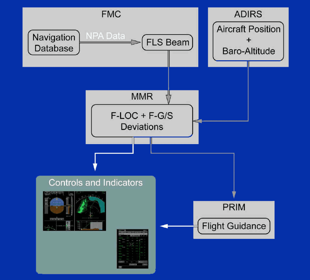
The layout of the FLS beam is based on the:
FLS Approach - The FLS beam corresponds to the final-approach flight leg of the Non Precision Approach (NPA). The FLS beam is defined by:
FIX INFO RADIUS with a large radius more than _____ NM, may not appear correctly on the ND.
FLS Approach - If the FMS does not compute the FLS beam, the FLS function is not available. The FMS message area displays the NO FLS FOR THIS APPR message.
For the CRZ flight phase, the FMS computes the Maximum Turbulence (MAX TURB) speed/Mach. The MAX TURB speed/Mach is the maximum speed/Mach to safely fly in a turbulent atmosphere. The MAX TURB speed/Mach is a protection against both inadvertent stall and structural damage. The MAX TURB speed/Mach depends on:
Each FMC has:
Some FMS data can be customized, by using the Airline Modifiable Information (AMI) file.
At power-up and during the PREFLIGHT flight phase, the default FMS speed mode is ECON with no CI value. Then, if the flight crew does not enter a CI value before the flight crew enters the ZFW value or before engine start, the FMS automatically:
FLS functions within FMS - The FMS Landing System (FLS) function provides the flight crew with cockpit indications and guidance to fly a:

FLS Beam - When the anchor point is a point that is stored in the navigation database, the anchor point is displayed in magenta.
When the anchor point is a point that is stored in the navigation database, the anchor point is displayed in green. The green color indicates that the anchor point is a flight plan waypoint. When the anchor point is a pseudo end point that is computed by the FMS, the anchor point is displayed in magenta. The magenta color indicates that the anchor point is a virtual point.
The RTA (Required Time of Arrival) is a time constraint that must be respected at the revised waypoint. The constraint can be to reach the waypoint AT, AT OR BEFORE, or AT OR AFTER the entered RTA. The flight crew can define an RTA at all waypoints of the destination flight plan (including the destination airport), except at the departure airport, the FROM waypoint, and the missed approach waypoints. There can be multiple RTAs per flight plan.
There can be only one RTA per flight plan. If there is already an RTA in the flight plan and the flight crew enters a new RTA on a different waypoint, the previous RTA is deleted, and the new one is taken into account.
Advertisement
If an RMP fails, the tuning information is still sent from the FMS to its onside navaids.
Up to latitude 73 degrees N(S), the flight crew can align the IRs without any particular procedures.
With the EFIS CP, the flight crew controls the graphical and textual FMS data that appear on the PFD.
With the EFIS CP, the flight crew controls the graphical and textual FMS data that appear on the ND.
Direct with Abeam selection - The CRS IN option creates a direct flight leg from the aircraft present position to intersect an inbound course (selected by the flight crew) of the target waypoint. The track of the direct flight leg is the current aircraft track. If the angle between the direct flight leg and the inbound course is less than ______, the FMS computes an intersection point (this intersection point is the INTCPT waypoint), the lateral HDG/TRACK mode is engaged, and NAV is armed.
The INTCPT waypoint is recomputed, when the flight crew changes the aircraft track. The NAV mode engages automatically, when INTCPT is sequenced. If the angle between the direct flight leg and the inbound course is more than 160 degrees no intersection point is computed, the lateral HDG/TRACK mode is engaged, and NAV is armed.
The FLS function is available only for approaches that are stored in the navigation database.
If the flight crew decides to exit the holding pattern immediately, the flight crew clicks on the IMMEDIATE EXIT button on the ACTIVE/F-PLN page. The FMS assumes that the aircraft will return immediately to the holding exit fix, and revises the predictions accordingly.
The CLOSEST AIRPORTS function computes the _____ database airports, that are closest to the current position of the aircraft.
The CRS OUT option creates a direct flight leg from the aircraft present position to intersect an outbound course (selected by the flight crew) of the target waypoint. The track of the direct flight leg is the current aircraft track.
The navigation database provides standard navigation data: Navaids, waypoints, airports, runways, airways, holding patterns, company routes, terminal area procedures (SID, STAR, approach), MSA, and MORA. This data is stored for:
FLS and ILS Modes and FLS Capability on the FMA - The PRIM and the ISIS send the AP/FD modes and the FLS capability to the PFD.
Only the PRIM sends the AP/FD modes and the FLS capability to the PFD.
Advertisement
FMS TRIP WIND - The trip wind is an average wind for the entire flight from:
The trip wind is defined as a headwind or tailwind component. The FMS uses the trip wind for prediction computation, as long as no climb, cruise, descent, or approach winds are entered.
INSERT NEXT WPT mode - If the flight crew inserts a flight plan waypoint, a direct flight leg is created between the revised waypoint and the inserted waypoint.
The ADIRS is able to provide TRUE heading(track), regardless of the aircraft latitude.
The ADIRS is able to provide MAG heading(track) between latitudes 82 degrees 30 min N and 60 degrees 30 min S, except in the vicinity of the magnetic pole.
When the aircraft flies on a holding pattern, the flight crew can make a revision of the holding pattern. This revision will create a temporary flight plan. The flight crew can check the new holding pattern in the temporary flight plan (on MFD and ND).
When the flight crew inserts the temporary flight plan, the aircraft keeps on flying on the old holding pattern. Only when the aircraft sequences the holding fix, the FMS takes into account and displays the updated holding pattern.
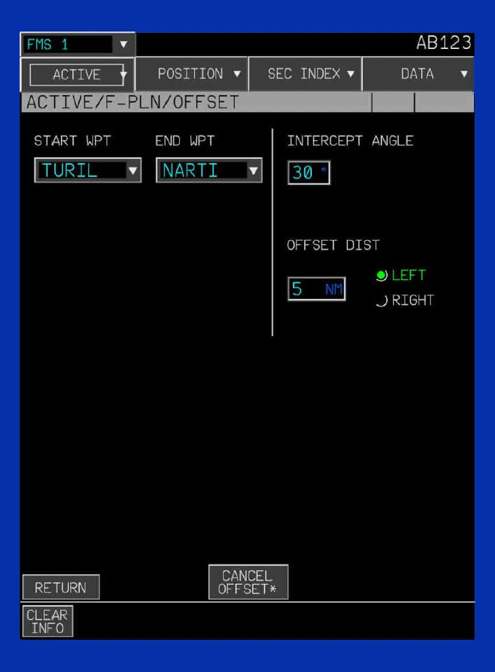
OFFSET Flight Planning - An existing offset path must be manually deleted if a revision of a flight plan causes the offset path to be no longer possible (for example: deletion of the start and the end waypoint).

An existing offset path is AUTOMATICALLY deleted if a revision of a flight plan causes the offset path to be no longer possible (for example: deletion of the start and the end waypoint).
When a flight plan has a departure procedure (RWY+SID+TRANS), and the flight crew changes the RWY, the FMS may automatically change or delete some elements of the SID. As a result, if the flight crew changes the RWY, they should check all of the elements of the departure procedure, and correct them, if necessary.
The ND can display the grid track in all ND display modes.
The ND can display the grid track in all ND display modes, except in PLAN mode. The ND displays the grid track, when all of the following occur: the north reference is TRUE and the aircraft is at a latitude above 65 degrees.
FLS Beam - The FMS sends the FLS beam to the ND. The FLS beam appears as a magenta dashed line with a length of:
OFFSET Flight Planning - The OFFSET revision is available for:
The flight crew cannot change the Cost Index (CI), when the DES, APPR, or GA flight phase is active.
Advertisement
FMS Winds - The flight crew uses the WIND revision to check, insert, and modify flight plan winds. Wind data must be entered to obtain correct flight plan predictions. The flight crew can enter an average trip wind for the entire flight, or can enter more precise wind data for the different flight phases and different waypoints of the flight plan cruise. What is the purpose of the "history winds"?
The FLS beam is a virtual beam that can be captured up to _____ from the destination. As the FLS beam is a virtual beam, the FLS beam can go through terrain obstacles.
When the flight crew inserts a DIR TO - CRS IN, the ADJUST DESIRED TRK OR HDG message is always displayed.
This message informs the flight crew that it is possible to adjust the aircraft heading/track to enable the computation of the INTCPT waypoint (if, after the heading/track change, the intersection angle becomes less than 160 °), or to change the position of the INTCPT waypoint (if it was previously computed).
FLS Approach - When the temperature at destination (that is entered on the APPR panel of the PERF page) is below the ISA temperature:
If no temperature is entered, the ISA temperature is considered at destination. The temperature correction is only done for the computation of the FLS beam and the F-G/S deviation, and does not change the barometric aircraft altitude on the PFD.
Direct with Abeam selection - When a latitude/longitude crossing, circle/radial intersection, or abeam waypoint is projected, it is recomputed by using the initial latitude/longitude and reference fix waypoint.
The MMR sends the FLS and ILS indications to the PFD.
The FMS has _____ types of holding pattern, based on _____ different ways to exit the holding pattern.
Departure Flight Planning - If the flight crew chooses to have no SID:
In the navigation database, the Final Descent Point (FDP) is the point in the approach procedure from which a constant descent path angle is defined.
Of the two active FMCs, one FMC is referred to as the "master", the other as the "slave". The selection of the master FMC is based on:
Advertisement
The FMS computes a cruise Mach when the cruise flight level is at or above _____.
Similarly, the FMS computes a cruise speed when the cruise flight level is below FL 250.
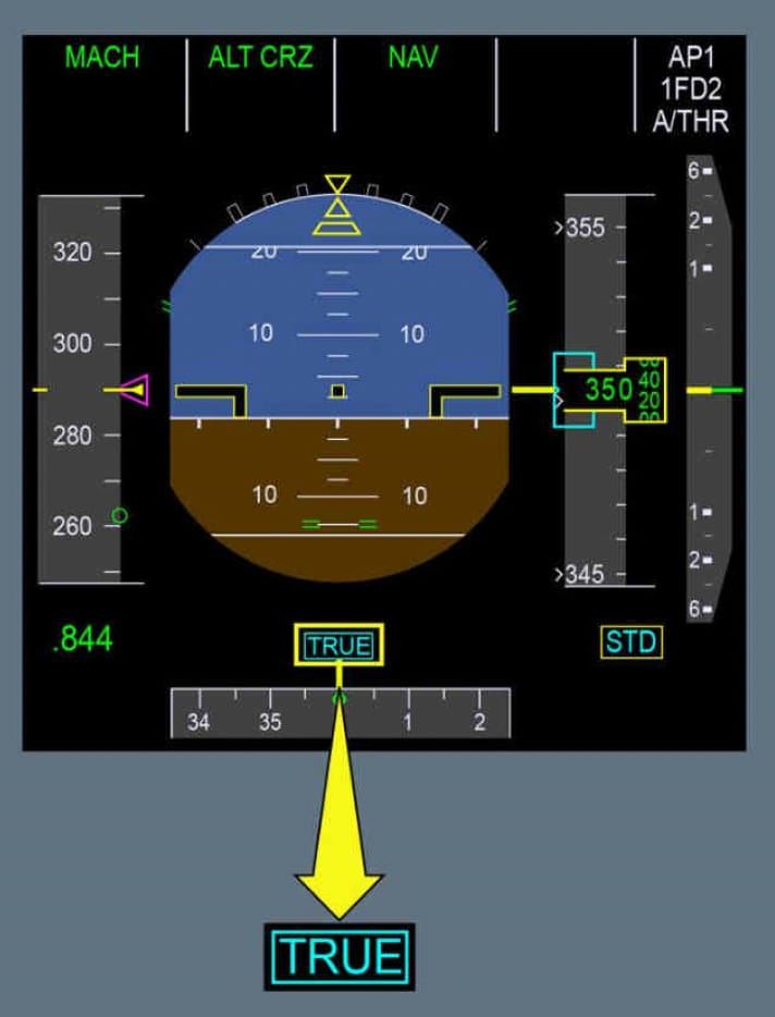
Before approach, if the cockpit north reference is TRUE:

The TRUE label above the PFD-ND heading scales flashes for 10 s at slat extension and the TRUE NORTH REF memo also pulses for 10 s at slat extension.
Navigation functions - The flight crew can manually tune the SLS.
The flight crew cannot manually tune the SLS.
For the ENGINE OUT scenario, the FMS computes the GDOT Engine-Out Maximum Flight Level (GDOT EO MAX FL). The GDOT EO MAX FL is the maximum flight level at which the aircraft can:
The ENGINE OUT scenario depends on the predicted altitude at the revised waypoint.
All pilot-stored elements are deleted, when all FMCs are shut down.
Flight Planning - When the aircraft moves to a flight plan discontinuity:
If no Constant Mach Segment (CMS) is defined in the flight plan, the managed speed/Mach target, from the T/C to the T/D, is the optimized speed/Mach (ECON, LRC, or RTA).
FLS Beam - Amongst all the conditions that are necessary to get the FLS beam appearing, the ND range selected by the flight crew on the ND range must be less than or equal to:
The FLS beam appears, when all of the following occur: the flight crew selected an NPA for the active flight plan, the flight crew pressed the LS pb on the EFIS CP, and the flight crew selected an ND range that is less than or equal to 80 NM in ARC or PLAN mode, or 160 NM in ROSE-NAV mode.
The flight crew can insert climb winds on:
The wind at Ground (GND) level can be entered as one of these levels. An altitude entry below 400 ft is considered as a ground level. The flight crew can also insert the history winds as the climb winds. The inserted history winds can always be changed by the flight crew afterwards. The climb winds can only be inserted, or changed before the CLB phase
The ND displays the entire holding pattern and its entry trajectory, only when:
In all other cases, the ND displays the holding pattern symbol.
Advertisement
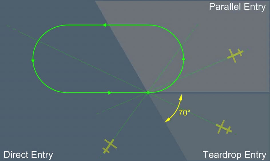
If the flight leg toward the holding entry fix has the opposite course of the holding inbound course, the aircraft will fly a parallel entry.

F-PLN page - A pseudo waypoint is displayed between parentheses, and has time, speed, altitude, and wind predictions. Some pseudo waypoints can be displayed in amber. For these pseudo waypoints, the amber color indicates that:
The T/C pseudo waypoint is the position at which the aircraft will reach:
The aircraft enters the holding pattern. When the flight leg parameter of the holding pattern is a time (and not a distance), the FMS revises the size of the holding pattern, based on the speed target at the holding entry fix.
When the selected speed/Mach control is engaged, the revision of the holding pattern size is based on the selected speed target. Each time the aircraft flies over the holding fix, the FMS updates the predictions for one more holding loop.
The pilot-stored elements database stores the waypoints, navaids, runways, and routes that the flight crew created. The contents of this database are limited to:
The contents of this database are limited to 99 waypoints, 20 navaids, 10 runways and 5 routes (with a maximum size of 30 flight plan elements per route).
There is no discontinuity in the lateral guidance if the flight crew manually changes the north reference, or if an automatic north reference switching occurs when entering the polar zone. The AP remains engaged in both cases. If TRUE is selected:
The flight crew can use the OVERFLY revision to ensure that the aircraft overflies a specific flight plan waypoint.
The OVERFLY revision is the 7th revision in the waypoint revisions menu on the F-PLN page.
When a flight is scheduled to cross high latitude areas (beyond 60 degrees of latitude), the flight crew must take various precautions, about the:
The Cost Index (CI) can vary from:
CI = 0 corresponds to the minimum fuel cost (maximum range). CI = 999 corresponds to the minimum time cost (minimum time).
FLS Approach - When the barometric reference is STD, the computation of the FLS beam and the F-G/S deviation is based on:
If no QNH is entered, a QNH of 1013 hPa (2992 in.hg) is considered for the computation of the FLS beam. When the barometric reference is QNH, the computation of the FLS beam and the F-G/S deviation is based on the current QNH.
Advertisement
RMP Failure - In FMS SINGLE mode, or in the case of communication failure between an FMS and its onside RMP:
The onside navaids are tuned via the onside RMP, and the offside navaids are tuned via a direct FMS-navaid connection.
FMS 1 can tune:
FMS 2 tunes the same equipment.
For RNP AR procedures strictly below 0.3 NM, the flight crew must:
RNP AR - The RNP AR function is basically RNP 0.1 capable. No indication informs the flight crew that the aircraft is RNP 0.1 capable.
The aircraft is capable to perform RNP AR operation down to 0.1 in takeoff, approach and/or missed approach.
The Airbus A350 has two FMCs: FMC A and FMC B.
The Airbus A350 has three FMCs: FMC-A, FMC-B and FMC-C. In normal operation FMC-A provides data to FMS 1. FMC-B provides data to FMS 2 and FMC-C is the backup FMC.
The PFD and the ND display graphical and textual information that is related to flight management. The upper part of the ND displays the lateral part of the flight plan, and the lower part of the ND (referred to as the VD) displays the vertical part of the flight plan.
On the upper part of the ND, the flight crew can make some changes to the lateral part of the flight plan via the KCCU.
The WHAT IF function enables the flight crew to assess the capability of the aircraft to reach a diversion airport in the case of a specific type of failure. The WHAT IF function is not available for both the active flight plan and the secondary flight plan.
The WHAT IF function is not available for the active flight plan. The flight crew uses the WHAT IF function to simulate a WHAT IF event for a secondary flight plan.
