The bank warning indicator is displayed when radio altitude is less than _____ and bank exceeds _____ degrees.
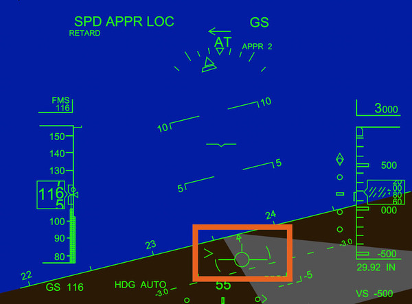
It is removed when the bank angle is less than 9 degrees or when the radio altitude is more than 100 feet.
The Pitch Target Marker (PTM) is displayed in pink and it is the attitude reference for takeoff. When the aircraft is airborne, the PTM is removed above _____. The PTM is also removed when flight pitch guidance (e.g. Flight Level Change (FLC) mode) is selected on the FCP.
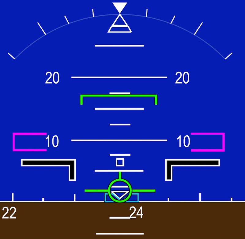
The PTM is also removed when flight pitch guidance (e.g. Flight Level Change (FLC) mode) is selected on the FCP.
The LVTO function displays ground roll guidance in low-visibility conditions. LVTO mode guidance stays active until:
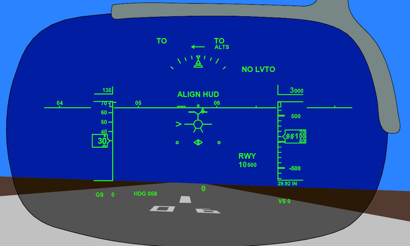
When aligned on the takeoff runway localizer beam, LVTO replaces LVTO ARM on the HUD combiner, the ground roll guidance cue and runway length remaining are displayed, and the localizer deviation scale repositions. On the PFD, LVTO is displayed in blue.
On the PFD, LVTO is displayed in green.
The combiner unit is stowed out of view when not in use, and is protected by a cloth cover when stowed. If there is a sudden deceleration, the combiner moves to the forward breakaway position to prevent head injury.
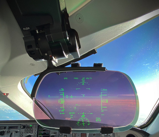
To return the combiner to the deployed or stowed position, the combiner latch lever is pushed, and the combiner is pulled to the deployed or stowed position.
What is the purpose of the 'line brackets' on the roll scale?

These markers are not displayed in direct mode.
The Flight Director (FD) guidance cue, shown on the HUD as a circle and wings, shows the lateral and vertical FD commands supplied by the Automatic Flight Control System (AFCS). It is similar to the FD guidance cue on the PFD. cue symbol extends past the FPV wings. The FD guidance cue is displayed 3 seconds after weight-off-wheels and for as long as FD modes are active.
An arrow shows the wind direction relative to the aircraft heading. The wind speed is displayed above the arrow when it is more than _____.
The current heading is displayed on the horizon line as a small inverted hollow triangle. The selected heading indicator (bug) is displayed on the horizon line. The selected course is displayed as a short arrow below the horizon line.
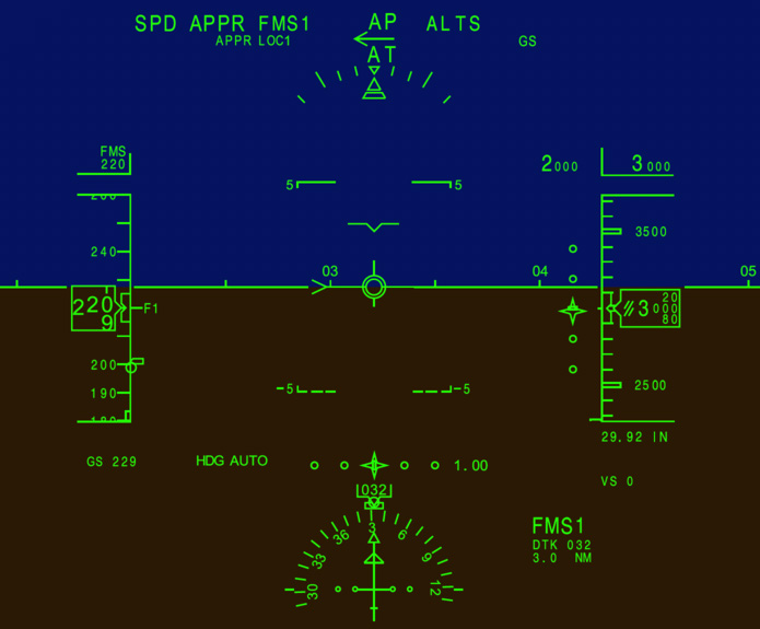
In the LVTO active mode, when the aircraft deviates more than _____ from the runway centerline (with ground speed of more than 40 kt), EXCESS DEV is displayed in the upper middle portion of the HUD – ADI. The ground roll guidance cue and localizer deviation pointer give corrective guidance.
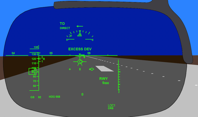
EXCESS DEV is displayed in amber on the ADI. When the deviation is corrected, and distance from the runway centerline is less than 22 feet, the EXCESS DEV indication is removed.
Advertisement
The HUD includes a DIM/BRT knob to control brightness. The DIM/BRT knob is on the combiner unit, on the upper inboard part of the arm. After the level has been manually set:
In all landing conditions, the FPV is displayed continuously while on the ground. The FPV becomes inactive (laterally locked and centered) on the ground when the ground speed is less than 60 kt. It is removed at less than _____.
Ground speed is displayed in small font in the lower left corner with a GS label. An invalid value is displayed as:
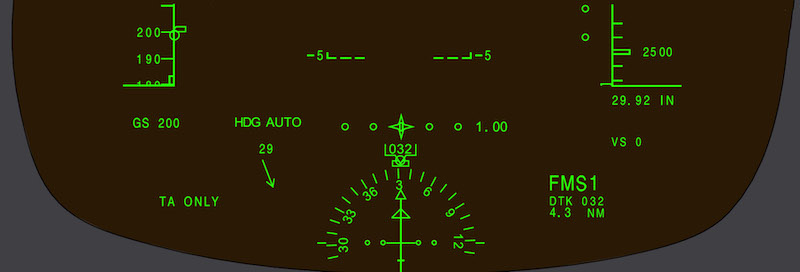
The HUD FPV, similar to the PFD FPV, is displayed as a circle with two horizontal lines that represent the wings and a vertical line to represent the stabilizer. The FPV moves within the ADI area to show the aircraft flight path in relation to the aircraft reference symbol. On takeoff, the FPV is displayed when the speed reaches _____.
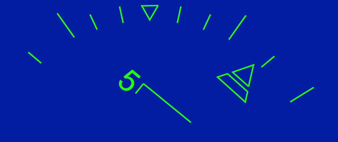
The roll scale tick marks are at 10, 20, 30, 45, and 60 degrees. The 60 degree bank angle tick marks are only displayed when the actual bank angle exceeds 40 degrees (left or right). If the 60-degree tick marks are displayed, they are removed when the bank angle is less than _____.
A 'NO FLARE' message is displayed and no flare guidance is shown on the HUD if the on-side radar altimeter fails.
A 'FLARE FAIL' message is displayed and no flare guidance is shown on the HUD if the on-side radar altimeter fails.
The approach path angle is displayed as a dashed horizontal line that is conformal to the outside visual scene. The glideslope angle is displayed on both sides of the line. The approach path angle line is displayed:
It moves laterally with the FPV so that the gap in the line remains laterally aligned with it. During the flare sequence, the approach path angle line is removed from the HUD, decluttering all non-essential information during the flare.
Tail strike pitch limit - If the tail strike pitch limit symbol and the aircraft reference symbol meet, it indicates a tail strike.
The vertical speed is displayed in small font with a VS label below the barometric correction readout. A minus sign identifies negative values. Like the PFD, the HUD displays a vertical speed scale on the right side of the altitude tape.
Unlike the PFD, the HUD does not display a vertical speed scale on the right side of the altitude tape.
Pitch chevron - The pitch chevron is an upward or downward pointing V that is part of the pitch tape. The pitch chevron indicates an excessive pitch attitude. The V point is at the +30-degree pitch line and the −20-degree pitch line. The tip of the V points in the direction of level flight. The chevron at +30 degrees becomes visible when pitch attitude reaches approximately +25 degrees, while the chevron at −20 degrees becomes visible when pitch attitude reaches approximately _____
Advertisement
Selection of TUNE/MENU on the Control Tuning Panel (CTP) opens the MENU page. With regards to the 'APPR PATH ANG' selection, when MAN mode is selected, the default value is −3 degrees, which can be updated by a value of between 0 and:
Tail strike pitch limit - The tail strike symbol is displayed during rotation either when the PTM is not displayed and the aircraft pitch angle approaches the tail strike angle by less than _____, or when the pitch rate is excessive.
Pitch Target Marker (PTM) - The Pitch Target Marker (PTM) is displayed as a split rectangular box. The HUD PTM symbol is displayed after the second engine start.
Unlike the magenta PTM on the PFD, the HUD PTM symbol is not displayed until rotation.
The LVTO function displays ground roll guidance in low-visibility conditions. When the LVTO function is selected ON, the LVTO mode annunciation is displayed on the HUD combiner to the right of the bank indication scale.
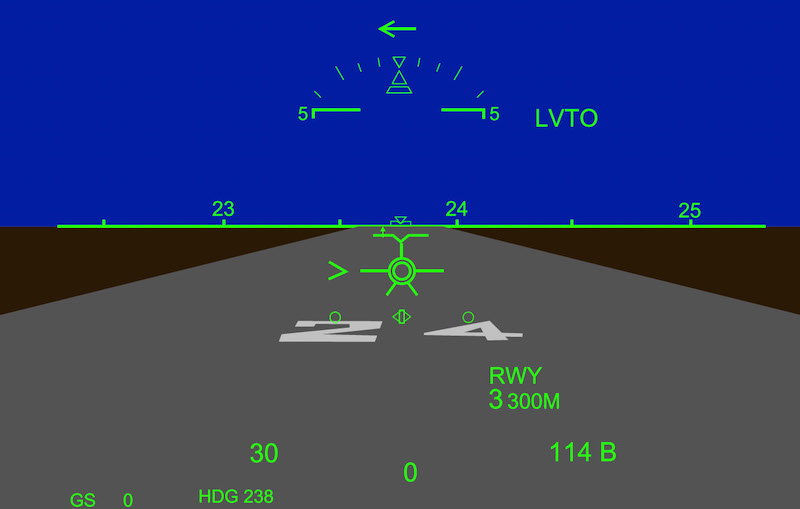
The flare cue gives guidance for the landing flare. It is displayed as two crosses and a solid and thick split line below the Flight Path Vector (FPV) at _____.

It rises as the aircraft descends below 80 feet RA. When it reaches the FPV, they always move together (grouped).
During landing, the deceleration scale is displayed when weight is sensed on the main landing gear, and is removed when speed decreases to less than _____.
A combiner alignment detector signals the overhead unit if the combiner is correctly aligned when in the operating position. An out-of-alignment condition causes the HUD to show an 'ALIGN HUD' message on the:
The message is removed when the combiner glass is repositioned so that it snaps into the detents.
Selection of TUNE/MENU on the Control Tuning Panel (CTP) opens the MENU page. With regards to RWY LENGTH, when FMS mode is selected, the value is set automatically from the selected departure runway in the FMS flight plan. When a value is not available:
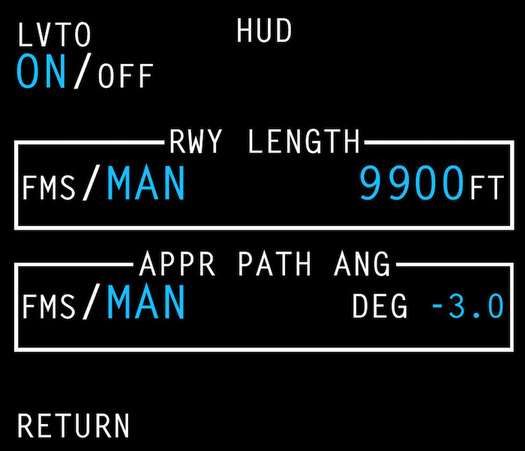
When MAN mode is selected, the value is set by the flight crew and it can range from 2000 to 20000 feet.
Information displayed on the HUD is focused at optical infinity. It is not necessary to refocus the eyes to see either the displayed symbols or outside the aircraft. When the head of the pilot is centered in the eye reference point, the entire display fits in the field of view:

During an engine failure at takeoff, the beta index is automatically displayed below the FPV _____. Both the beta index and the roll scale slip and skid indicator are displayed as hatched trapezoids.
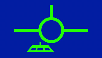
When slats/flaps are fully retracted, both the beta index and the roll scale slip and skid indicator are displayed as hollow shapes.
