The hydraulic isolation systems ensure the flight crew can:
The Ram Air Turbine (RAT) only provides hydraulic power to the center hydraulic system primary flight controls.
When pulled, the only action of the engine fire switch is to close the engine–driven pump hydraulic supply shutoff valve.
Pulling the engine fire switch closes the engine–driven pump hydraulic supply shutoff valve and depressurizes the engine–driven pump.
What is the nominal pressure of all three hydraulic systems?
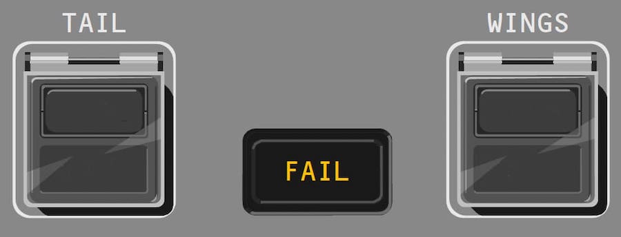
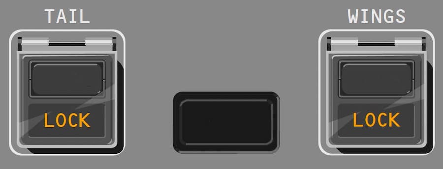
Flight Control Surface Lockout Switches - What does this indicate?

No flight crew normal or non–normal procedures require operation of the flight control surface lockout switches. These switches are for ground maintenance use only.
Hydraulic Display Quantity (QTY) – When is the "LO" indication displayed?

What is the primary source of the center hydraulic system?
The RAT provides hydraulic and electrical power:

The RAT can be deployed manually by pushing the RAM AIR TURBINE switch on the hydraulic panel. A spring-loaded actuator is used to deploy the RAT either automatically or manually. Once deployed, the RAT cannot be stowed in flight.
What component supplies fluid to the engine-driven hydraulic pump?
Flight Control Surface Lockout Switches - What does this indicate?

No flight crew normal or non–normal procedures require operation of the flight control surface lockout switches. These switches are for ground maintenance use only.
Advertisement
Which of the following components is not powered by the hydraulic systems?
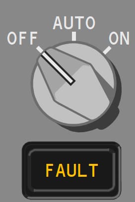
If illuminated amber what does indicate the C2 Pump FAULT light?

______ provide supplementary hydraulic power for periods of high system demand.
The left and right hydraulic systems each have a demand pump. The demand pumps are electric motor–driven (EMPs).
What is the difference between the left and right hydraulic systems?
The left and right hydraulic systems are identical. They differ only in the components they power.
The center hydraulic system does not power:
The hydraulic systems power the:
In the event of a leak in the center hydraulic system:
The RAT, when deployed, provides _____ hydraulic power to the primary flight controls connected to the center hydraulic system.
Hydraulic Display Quantity (QTY) – When is the "OF" displayed?

The _____ serve as a backup for the primary pumps.
Advertisement
Hydraulic fluid is supplied to each hydraulic pump from the associated system reservoir. The reservoirs are pressurized by pump outlet pressure.
Hydraulic Display Quantity (QTY) – What is the true statement?

Hydraulic fluid is supplied to each hydraulic pump from the associated system reservoir. The reservoirs are pressurized by pump outlet pressure.
The center hydraulic system is powered by:
Left and right hydraulic system primary pumps are:
The center hydraulic system pumps:
Center Hydraulic System Electric Pumps - The two center pumps alternate as a primary pump and demand pump.
What is the function of the ELEC DEMAND L and R pump selectors?
Center Hydraulic System Non–Normal Operation - The center hydraulic system has isolation functionality in the event of a leak or overheat. The isolation valves operate automatically and cannot be controlled by the flight crew.
The center hydraulic system has isolation functionality in the event of a leak (not or overheat).
What the primary source for the left and right hydraulic systems?
Advertisement
The left and right hydraulic system demand pumps operate under the following conditions:
The demand pumps are:
Which of the following components is powered by more than one hydraulic system?
What hydraulic system powers the nose gear steering?
The center demand pump operates:
There are certain airplane failure modes which require one or more of the demand pumps, left, right or center to load shed to allow the electrical system to provide power to other systems. The indication is LOAD SHED showing on the hydraulic synoptic next to the demand pump symbol.
How many hydraulic systems does the Boeing 787 have?
Note: The airplane has three independent systems: left, right, and center.
Hydraulic system indications are displayed by pushing the systems (SYS) display switch, then selecting either the status (STAT) synoptic key or the hydraulic (HYD) synoptic key.
Hydraulic Display Quantity (QTY) – When is the "RF" indication displayed?

