Electric Hydraulic Pump OVERHEAT Lights - What does this light indicate?

Power Transfer Unit (PTU) - The PTU uses system B pressure to power a hydraulic motor–driven pump, which pressurizes system A hydraulic fluid.
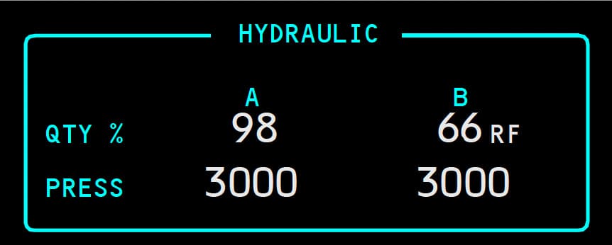
System A Hydraulic Leak - If a leak develops in the engine–driven pump or its related lines, a standpipe in the reservoir prevents a total system fluid loss. With fluid level at the top of the standpipe, the reservoir quantity displayed indicates approximately _____
System A hydraulic pressure is maintained by the electric motor–driven pump.
The RFF indication is displayed:

Loss of an engine-driven hydraulic pump and a high demand on the system may result in an intermittent illumination of the LOW PRESSURE light for the remaining electric motor-driven hydraulic pump.
The flight control LOW PRESSURE light, Master Caution light, and the FLT CONT and HYD system annunciator lights also illuminate.
The amber LOW pressure light for the No.1 Engine Driven Hydraulic Pump illuminates. What should you do?

If the hydraulic system is not properly pressurized, foaming can occur at higher altitudes. Foaming can be recognized by:
Power Transfer Unit (PTU) - The purpose of the PTU is to supply the additional volume of hydraulic fluid needed to operate _____ when system B engine–driven hydraulic pump volume is lost.
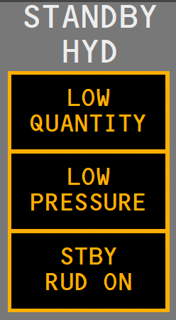
Standby Hydraulic System Leak - The LOW QUANTITY light illuminates when the standby reservoir:
The ELEC 2 (system A) or ELEC 1 (system B) pump ON/OFF switch controls the related electric motor–driven pump. If an overheat is detected in either system, the related OVERHEAT light illuminates.
Advertisement
STBY RUD ON Light - When illuminated amber, it indicates the standby hydraulic system is commanded on to pressurize the standby rudder power control unit.

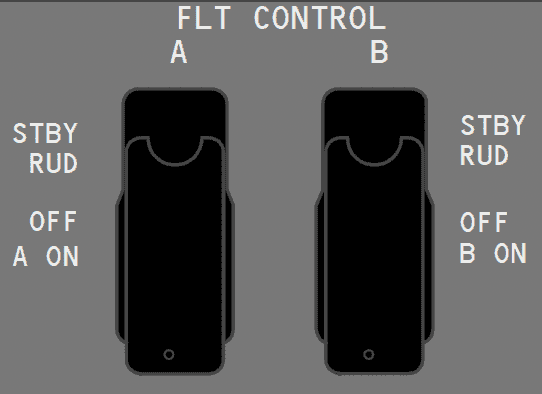
If one FLIGHT CONTROL switch is moved to STBY RUD:

STANDBY HYDRAULIC LOW QUANTITY Light - What is the true statement?

Hydraulic fluid used for cooling and lubrication of the pumps passes through a heat exchanger before returning to the reservoir. The heat exchanger for system A is located in main fuel tank No. 2 and for system B is in main fuel tank No. 1.
The heat exchanger for system A is located in main fuel tank No. 1 and for system B is in main fuel tank No. 2.
Standby Hydraulic System Leak - System B continues to operate normally, however, the system B reservoir fluid level indication decreases and stabilizes at:
System A Hydraulic Leak - If a leak develops in the engine–driven pump or its related lines, a standpipe in the reservoir prevents a total system fluid loss. With fluid level at the top of the standpipe, the reservoir quantity displayed indicates approximately _____
System A hydraulic pressure is maintained by the electric motor–driven pump.
Landing Gear Transfer Unit - The system B engine–driven pump supplies the volume of hydraulic fluid needed to operate the landing gear transfer unit when all of the following conditions exist:
System B Hydraulic Leak - A leak in system B can significantly affect the operation of the standby hydraulic system.
A leak in system B does not affect the operation of the standby hydraulic system.
An engine–driven hydraulic pump supplies approximately _____ the fluid volume of the related electric motor–driven hydraulic pump.
In addition to hydraulic system A and B, the rudder can also be powered by the standby hydraulic system through the:
Advertisement
Both A and B hydraulic systems have an engine–driven pump and an AC electric motor–driven pump. The system A engine–driven pump is powered by the No. 2 engine and the system B engine–driven pump is powered by the No. 1 engine.
The system A engine–driven pump is powered by the No. 1 engine and the system B engine–driven pump is powered by the No. 2 engine.
Variations in Hydraulic Quantity Indications - During normal operations, variations in hydraulic quantity indications occur when:
These variations have little effect on systems operation.
The hydraulic brake pressure indicator displays accumulator nitrogen pre-charge pressure of 1000 psi and:
Standby Hydraulic System Leak - If a leak occurs in the standby system, the standby reservoir quantity decreases to _____
In case of loss of system A:
STANDBY HYDRAULIC LOW PRESSURE Light - When illuminated amber:

Minimum fuel for ground operation of electric motor-driven pumps is _____ in the related main tank.
Standby Hydraulic System - The standby hydraulic system is provided as a backup if system A and/or B pressure is lost. The standby system can be only activated automatically.
The standby system can be activated manually or automatically.
System A Hydraulic Leak - If a leak develops in the electric motor–driven pump or its related lines, or components common to both the engine and electric motor–driven pumps:
The standby hydraulic system uses a single electric motor–driven pump to power:
Advertisement
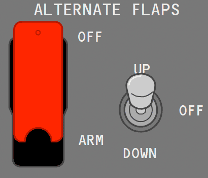
ALTERNATE FLAPS Master Switch - When placed in the ARM position, the ALTERNATE FLAPS Master switch:

